Digital Panel Meters FAQ
Q. With the UDM meter, what is the action of the digital filter parameters on the measure value?
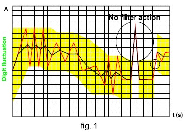
The first filter parameter is Fil.S and defines the operating range of the filter. This operating range is represented as a yellow band in figure 1 (each small square is one digit). Until the measured value (red curve in figure 1) is within this band, the filter is active; as soon as the value is outside this band, the filter is deactivated and a new band will be active around the new value. The proceedure to set this parameter is to look at the size of the fluctuation (in digits) and use this value (8 in figure 1 as an example). The second parameter is Fil.C and represents the filtering coefficient. The higher is Fil.C, the smoother is the curve of the displayed values (black in figure 1). There is not a theoretical rule to define this parameter, it is to be set on the field: however a rough suggestion is to start with the same value of the Fil.S coefficient and then increase it until the desired stability is reached.